

Radio 2eGM Torn e B Viervilles
English Translation
 |
Historique Voir ICIhttp://www.armyradio.com
History Click HERE
Article Tiré du site
Tornister Empfanger B Torn Eb
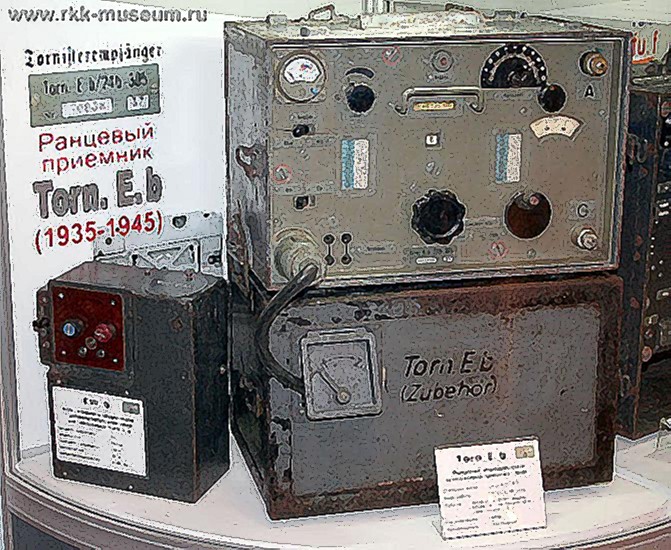
Probably the most commonly encountered German radio is the Tornister empfanger b set. We will use the original German designation of the receiver we are going to discuss now. The photograph shows a front view of the set. You see that the set consists of two units above each other. The cabinets meant to be carried on the back of a soldier-that house the units are called "Tornister' in German.
Actually in the photograph you see two half "Tornisters", one housing the receiver and the other the power supply. Empfanger" is the German word for receiver. And the letter 'b' in the designation simply indicates which receiver. Mostly the designator was shortened to "Torn E b" and that is what we will use. The Torn E b was created around 1935/36. It was in general use with the German Signal Corps, but also at higher army staffs, police and traffic control authorities. It was a popular set, produced in great numbers and one of the few sets that found their way to amateur service in Europe in post-war stations.
It is a tuned radio frequency (t.r.f.) set with four filament type tubes that were run from a 2 volt battery at 0.2 A. each. So the whole radio consumed about 0.8 A. from the battery. The anode current came from a 90 V. dry battery at a consumption of about 12 Ma. It was also possible to generate the h.t. from the 2 V. battery via a vibrator unit and that is what you see in photograph . The vibrator unit is on the bottom shelf of the lower cabinet. Still another possibility was to run the whole set from a 12 volt automobile battery, also with a vibrator for the HT.
The set covers the frequency band 100-6970 kHz in eight ranges. The actual coverage of each sub-band is as follows:
( Band l ) 97-175kHz
( Band 2 ) 172-310kHz
( Band 3 ) 306-552kHz
( Band 4) 541-977kHz
( Band 5 ) 958-1720 kHz
( Band 6 ) 1685-3030 kHz
( Band 7 ) 2940-4760 kHz
( Band 8 ) 4420-6970 kHz
 |
 |
| Torn e B Freue | Torn e B Spät |
There are three tuned circuits of which the variable tuning capacitors are ganged. We also find three sets of eight coils, one set for each subband. The coils with their associated fixed and trimmer capacitors are housed in a coil turret that can be clearly seen in the photograph . This picture shows several of the features that we mentioned in the previous section.
The coil turret is of cast alloy and contains completely screened compartments for each coil. The contacts are supported on cylindrical ceramic bars. The three gang tuning capacitor is also completely screened. You see the shaft bearing on the backside of the capacitor at the lower left. You also notice the bases of the four tubes. The two r.f.s and the detector tube are at the left, the a.f. tube at the right.
The tubes disappear completely in the tube holders. They can be withdrawn by means of the circular knobs that are part of the moulded tube base. The two r.f. stages and the detector stage are also completely screened. The extensive screening and de-coupling leads to an extremely stable set with no trace of undesired feedback between stages.
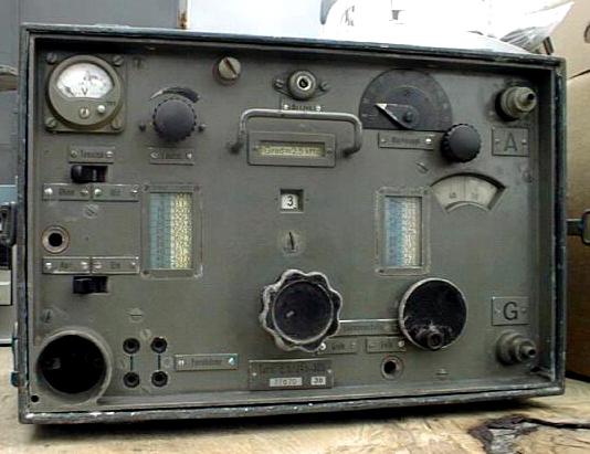
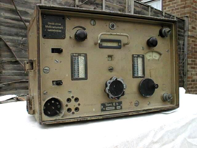
Let us again take a look at the front . The big knob at the lower centre controls the coil turret. Immediately above it the selected sub-bands number is shown in a little window. Left and right of centre you see windows that display a table; this gives the frequency that corresponds to the reading of the fine tuning dial that revolves with the tuning capacitor, seen at the right.
The table lists the frequency in increments of 5 dial divisions. But for a finer reading we can extrapolate between these increments; in a fourth window, immediately above the one that shows the sub-band number, we read how many kilohertz correspond to one dial division. For sub-band 1 this is 0.8 kHz, as you may be able to read from the photograph.
The knob called "Ruckkoppl" at top right controls the regeneration of the detector stage, number 55 in the circuit diagram. Any of you who have used a t.r.f. set know that the joy or misery you derive from it is determined in a major part by the action of the regeneration control. The set should slide smoothly into oscillation, without thumb or backlash, that is to say the detector should start and stop oscillation at the same position of the control.
These desirable features are dependent upon a number of factors in the circuit, as any of you old-timers can testify. But the German designers of t.r.f. sets certainly knew the secret of making a fine regeneration control. The one on the Torn E b, or any German t.r.f. set for that matter, is a pure joy to use. Fine control is assisted even more by a slow motion drive on the regeneration capacitor!
The knob with the crank turns the tuning capacitor via a 1:19 slow motion drive. This operates with great precision and with a smooth feel. Nevertheless it was at this point that the author had some criticism on the receiver; at the high end of the frequency band covered by the set near 7 MHz, one revolution of the tuning control changes the frequency by I some 200 kHz and this is too much for easy tuning of s.s.b. signals.This criticism is quite unfair, of course, as at the time the receiver was developed s.s.b. was unknown, at least for military applications. Still I found a way of fine tuning the set; as with most t.r.f. sets at high frequencies the regeneration control pulled the receiver tuning somewhat and this could be used as fine control.
The control marked "Lautst" is the gain control. It varies the screen grid voltage of both r.f. amplifier tubes. This works very well and avoids the possibility of overloading the detector. Top centre we find the antenna trimmer with screw driver adjustment. It is marked 20 in the circuit diagram. For telegraphy an audio filter, tuned at 900 Hz, can be brought into the circuit by means of the switch "Tonsieb." The filter consists of a parallel tuned circuit with coil 62 and capacitor 63. It is very effective on c.w.
Voir Aussi Autres Photoscopes See Also Others Walk Around
2eGM Torn e B Viervilles
2eGM Torn E b 24b Bayeux
2eGM Torn e B Spät Montélimar
2eGM Torn e B Spät Saumur Montélimar